Reading guide
Distribution transformer, referred to as "distribution transformer". A static electrical apparatus in distribution system which transforms AC voltage and current according to the law of electromagnetic induction to transmit AC energy. Distribution transformer is usually a power transformer which operates in the distribution network with voltage level of 10-35kV (mostly 10kV and below), and the capacity of 6300KVA and below directly supplies power to the end user.
1. basic introduction of power distribution
1.1 definition
Distribution transformer, referred to as "distribution transformer", refers to a static electrical apparatus in which alternating current energy is transmitted by changing AC voltage and current according to the law of electromagnetic induction. Some areas call power transformers with voltage levels of less than 35 kV (mostly 10kV and below), which are referred to as "Distribution Transformers" or "Distribution Transformers". The place and place where the "distribution transformer" is installed is not only a substation. The distribution transformer should be installed on the column or on the ground in the open air.
▲ distribution knowledge structure
(click to enlarge the reading)
1.2 structure
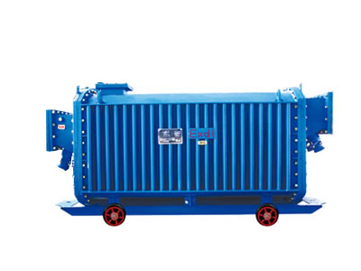
This small edition introduces the structure of oil immersed distribution transformer, which can be divided into body, oil storage cabinet, insulating sleeve, tap switch, protection device, etc. As shown in the figure below
Structure decomposition of distribution transformer
(click to enlarge the reading)
1.2.1 body
The main body consists of three parts: core, winding and insulating oil. Winding is the circuit of transformer, and core is the magnetic circuit of transformer. The two constitute the core of the transformer, namely the electromagnetic part.
1.2.1.1 iron core
The core is the main magnetic circuit part of transformer. It is usually made of hot rolled or cold rolled silicon steel sheet with high silicon content, thickness of 0.35 or 0.5mm and insulating paint coated on the surface. The core is divided into two parts: iron core column and yoke. The core column is covered with winding and the yoke is used for closing magnetic circuit. The basic forms of core structure are of the core type and the shell type.
▲ core structure
1.2.1.2 winding
Winding is the circuit part of transformer, usually made by insulating flat copper wire or round copper wire on the winding die. The winding is set on the transformer core column, the low voltage winding is in the inner layer, the high-voltage winding is set on the outer layer of the low-voltage winding, between the low-voltage winding and the iron core, between the high-voltage winding and the low-voltage winding, all of which are separated by the sleeve made of insulating materials to facilitate the insulation.
▲ winding structure
1.2.1.3 insulating oil
The composition of transformer oil is very complex, mainly composed of naphthenic, alkane and aromatic hydrocarbon. Transformer oil plays two roles in distribution transformer: one is to play an insulation role between transformer winding and winding, winding and core and oil tank. Second, the transformer oil will generate convection after heating, which will heat the core and winding of the transformer. There are three specifications of transformer oil commonly used, which are No. 10, 25 and 45, whose designation indicates the temperature of the oil when it starts to set at zero, for example, oil "25" indicates that the oil starts to set at minus 25 ℃. The oil specification should be selected according to the local climate conditions.
1.2.2 oil storage tank
The oil tank is installed on the top cover of the tank. The volume of the oil tank is about 10% of the tank volume. There is a pipe connection between the oil tank and the oil tank. When the volume of transformer expands or shrinks with the change of oil temperature, the oil storage tank plays the role of oil storage and oil supplement, ensuring that the core and winding are immersed in oil; meanwhile, the contact surface between oil and air is reduced due to the installation of oil storage tank, and the deterioration speed of oil is reduced.
Oil level standard line with oil temperature of -30 ℃, 20 ℃ and +40 ℃ is arranged beside the glass pipe, indicating the oil level height that the transformer is not put into operation; the standard line mainly reflects whether the oil quantity is sufficient when the transformer is running at different temperatures.
The oil storage tank is equipped with breathing holes to make the upper space of the oil tank connected with the atmosphere. When the transformer oil is hot expanded and cooled, the air at the upper part of the oil storage tank can be accessed through the breathing hole, and the oil level can rise or fall, so as to prevent the oil tank from deformation or damage.
1.2.3 insulating sleeve
It is the main insulation device outside the transformer box, and most of the transformer insulating casings are porcelain insulated casings. Through high and low voltage insulating sleeve, the transformer leads of high and low voltage winding are led from the tank to the outside of the tank, so that the transformer winding is insulated from the ground (shell and iron core), and it is also the main part of the fixed lead connecting with the external circuit. The high pressure porcelain sleeve is relatively tall and the low pressure porcelain sleeve is relatively short.
1.2.4 tap
The device of transformer high voltage winding changing tap and adjusting tap position can increase or decrease the number of turns of primary winding to change the voltage ratio and adjust the output voltage. After the transformer is out of operation and disconnected from the grid, the tap changer position is manually changed, and the voltage regulation without load is called the adjustment of output voltage.
1.2.5 protection device
1.2.5.1 gas relay
The gas relay is installed in the middle of the connecting pipe between the transformer oil tank and the oil storage cabinet, and is connected with the control circuit to form a gas protection device. The upper contact of gas relay and light gas signal constitute a separate circuit. The lower contact of gas relay is connected with the external circuit to form heavy gas protection. Heavy gas action causes the high voltage circuit breaker to trip and send out the heavy gas action signal;
1.2.5.2 riot control tube
Riot protection tube is a kind of safety protection device of transformer, which is installed on the large cover of transformer. The riot tube is connected with the atmosphere. In case of failure, the heat will vaporize the transformer oil, and the gas relay will be triggered to send out alarm signal or cut off the power supply to avoid the oil tank burst.
2. classification
2.1 classification by installation location
Distribution transformers are divided into indoor and outdoor according to the installation position.
Outdoor installation is divided into platform type, pole tower type and floor type (including pre installed type).
2.1.1 pole tower type
The pole tower type is to install the transformer on the frame of the pole. It can be divided into single rod type and double bar type.
When the capacity of distribution transformer is 30KVA or less (including 30KVA), the single pole distribution transformer stand is generally adopted. Install the distribution transformer, high voltage drop fuse and high voltage arrester on a cement pole, and the rod body shall be inclined 13 ° -15 ° to the opposite direction of the assembled distribution transformer.
When the capacity of distribution transformer is 50KVA ~ 315KVA, the double pole type distribution transformer station is generally used. The distribution transformer station is composed of one main pole cement pole and another auxiliary pole. The main pole is equipped with high voltage drop fuse and high voltage down lead, and the secondary reverse lead is provided on the auxiliary pole. The double pole distribution transformer station is strong through single pole distribution transformer.
The advantages of pole tower installation are: less land occupation, no enclosure or fence around, high live part from the ground, and no accident. Disadvantages: the steel used for the platform is more and the cost is higher.
2.1.2 pier type
The pier type is a square pier with masonry under the transformer pole, which is 0.5-1m, and the transformer is placed on it. Generally, the transformer with 315KVA or above is installed.
Let's see the original simple pier transformer installed in rural areas:
Attention shall be paid to the installation of pier type transformer:
(1) A firm fence or enclosure of not less than 1.8m shall be installed around the transformer. The door shall be locked and kept by a special person.
(2) The fence and enclosure shall be sufficient safe operation distance from the transformer.
(3) Warning signs such as "high voltage danger, no climbing" shall be hung on the pole or fence to prevent people and animals from approaching.
The advantages of pier installation are low cost and easy to maintain and repair. Disadvantages: there are many land occupation, and the surrounding area should be equipped with barriers. Small animals can easily climb to the charged part and be prone to external force damage accidents.
2.1.3 floor type
Floor type refers to putting transformer directly on the ground, and high voltage down lead, drop fuse and arrester are all on the line terminal pole.
Attention shall be paid to the installation of floor type transformer:
(1) Reliable barriers must be installed around the transformer, and the doors shall be locked and kept by special personnel.
(2) Warning signs such as "high pressure danger, no climbing" shall be hung outside the barrier.
(3) Since the live part of the transformer is very low from the ground, it is necessary to enter the barrier after the power supply is cut off.
2.2 electricity is classified according to cooling mode
According to the cooling mode, it can be divided into oil immersed and dry-type transformers.
Oil immersed transformer relies on oil as cooling medium, such as oil immersion self cooling, oil immersed air cooling, oil immersed water cooling, forced oil circulation, etc. Dry type transformer relies on air convection to cool naturally or increase fan cooling, and is mainly used for high-rise buildings, high-speed toll station power, local lighting, electronic lines and other small capacity transformers.
2.2.1 oil immersed transformer is divided into the following types according to the shell type:
1) Non enclosed oil immersed transformer: it mainly has series products such as S8, S9 and S10, which is widely used in industrial and mining enterprises, agriculture and civil buildings.
2) Closed type oil immersed transformer: it mainly includes S9, S9-M, s10-m and other products, and is mainly used in places with many oil and chemical substances in the petroleum and chemical industries.
3) Sealed oil immersed transformer: mainly bs9, s9-, s10-, s11-mr, SH, sh12-m and other products, can be used for distribution in various places such as industrial and mining enterprises, agriculture, civil buildings, etc.
2.2.2 dry type transformer is divided into three parts according to insulation medium:
1) Sealed coil dry type transformer: mainly includes series products such as scb8, SC (b) 9, SC (b) 10, scr-10, etc., which are suitable for high-rise buildings, commercial centers, airports, stations, subway, hospitals, factories and other places.
2) Non enveloped coil dry type transformer: mainly SG10 series products, suitable for high-rise buildings, commercial centers, airports, stations, subway, petrochemical and other places.
2.3 classification of voltage regulation mode
According to the voltage regulation mode, it can be divided into on load voltage regulation and no load voltage regulation.
The so-called no load voltage regulation and on-load voltage regulation are the voltage regulating methods of transformer tap changer. The difference is that the no load voltage regulating switch does not have the ability to change gear with load, and the transformer must be cut off when shifting gear. The on load tap changer can switch gears with load.
2.4 Phase Classification
According to the number of phases, it can be divided into single-phase transformer and three-phase transformer.
Single phase transformer is one-phase transformer, which is that primary winding and secondary winding are single-phase winding transformers. Single phase transformer is simple in structure, small in volume and low in loss, mainly because of small iron loss, which is suitable for application and popularization in low voltage distribution network with low load density.
Three phase transformer is used for raising and lowering voltage of three-phase system. Three phase transformer, generally has three windings, its connection method is divided into triangle, star, linear triangle, etc. the voltage phase difference of three windings is 120 degrees, that is, the common three-phase 380 volt connection mode. The core is traditionally in the form of three-phase three core, three-phase five core column, gradual opening line, etc.
3. working principle
The transformer consists of core (or core) and coil, and the coil has two or more windings, among which the winding connected with power is called primary coil, and the other winding is called secondary coil. It can transform AC voltage, current and impedance. The simplest core transformer is composed of a soft magnetic material core and two coils with different turns set on the core, as shown in the following figure.
The core of iron is used to strengthen the magnetic coupling between the two coils. In order to reduce the eddy current and hysteresis loss in iron, the core is made of laminated silicon steel coated sheet; there is no electrical connection between the two coils, and the coil is made of insulated copper wire (or aluminum wire). One coil is connected to AC power supply, which is called primary coil (or original coil), and the other coil connected electrical appliance is called secondary coil (or secondary coil). The actual transformer is very complex, and there are inevitably copper loss (coil resistance heating), iron loss (core heating) and magnetic leakage (magnetic induction line closed by air), etc. in order to simplify the discussion, only ideal transformer is introduced here. The ideal transformer is established under the following conditions: ignore the flux leakage, ignore the resistance of the original and secondary coils, ignore the loss of the core, and ignore the no-load current (the current in the primary coil of the secondary coil open circuit). For example, when the power transformer is in full load operation (rated power of the secondary coil output), it is close to the ideal transformer.
Transformer is a static electrical appliance made of electromagnetic induction principle. When the original coil of transformer is connected to AC power supply, alternating magnetic flux is generated in the core of iron, and the alternating flux is represented by φ. The φ in the primary and secondary coils is the same, and φ is also a harmonic function, and the table is φ = φ MSIN ω t. According to Faraday's electromagnetic induction law, the induced EMF in the original and secondary coils is e1=-n1d φ /dt, e2=-n2d φ /dt. Where N1 and N2 are turns of the primary and secondary coils. It can be seen from the figure that u1=-e1, u2=e2 (the physical quantity of the original coil is represented by the lower scale 1 and the physical quantity of the auxiliary coil is represented by the lower scale 2). The complex effective values are u1=-e1=jn1 ω Φ, U2 = e2=-jn2 ω Φ, which makes k = N1 / N2, which is called the transformer ratio. From the above formula, u1/ u2=-n1/n2=-k, that is, the ratio of the effective value of the voltage of the transformer's primary and secondary coils is equal to the ratio of turns and the phase difference between the voltage of the original and secondary coils is π.
Then we get the following:
U1/U2=N1/N2
Under the condition that no-load current can be ignored, there is i1/ i2=-n2/n1, that is, the effective value of the current of the primary and secondary coils is inversely proportional to the number of turns, and the phase difference π.
And then it can be obtained
I1/ I2=N2/N1
The power of the original and secondary coils of the ideal transformer is equal to p1=p2. It shows that the ideal transformer has no power loss. The actual transformer always has loss, and its efficiency is η = P2 / P1. The efficiency of power transformer is very high, which can reach more than 90%.
4. characteristic parameters
Rated capacity
Refers to the output power of transformer in working state, expressed by apparent power. Expressed in Sn, in KVA or VA.
Rated voltage
Refers to the voltage applied between the outgoing terminals of single-phase or three-phase transformer. Expressed in UN in kV or v. The primary rated voltage is expressed as un1 and the secondary rated voltage is expressed as un2.
Rated current
Refers to the current at the outgoing terminals of primary and secondary winding of transformer under rated capacity and allowable temperature rise, expressed in, in Ka or a. The primary winding current is expressed by in1 and the secondary winding current is expressed by iun21.
Rated frequency
The operating frequency specified in the design of batch transformers. Expressed in Hertz (Hz) in n. The rated frequency in China is 50Hz.
No load loss
No load loss is also called iron loss. When the rated frequency baby voltage is applied to the terminal of one winding and the outgoing line of the other side winding is open, the active power absorbed by the transformer is represented by P0, in W or kW. The no-load loss is mainly hysteresis loss and eddy current loss in the core. The value is closely related to the material and manufacturing process of the core. It is generally believed that the no-load loss of a transformer will not change with the load size.
No load current
When the transformer is open, there is still a certain current in the primary stage, which is called no-load current. The no-load current consists of magnetization current (which produces flux) and iron loss current (caused by core loss). For 50Hz power transformer, the no-load current is basically equal to magnetization current. Expressed in I0. Generally, it is expressed as the percentage of no-load current in rated current, i.e. I0 (%) = (i0/in) × 100%. The larger the transformer capacity, the smaller the value.
Load loss
Load loss is also called short circuit loss and copper loss, which refers to when the winding with tap is connected to its main tap position and connected to the rated frequency

 Service