Release time:2021-03-26 15:30:11 Popularity: Source:未知
1. Cause of partial discharge, because the insulators and metal bodies in transformers often have some sharp corners and burrs, the electric charge will be concentrated at the sharp corners or burrs under the effect of electric field intensity, this leads to partial discharge of transformer because under the action of High Electric Field Strength, the charge capacity concentrates to the sharp corner, which causes discharge. During vacuum casting of epoxy insulated dry-type transformer, if the process control is not good, there will be some bubbles inside and partial discharge will occur. In general, there are some tiny air gaps in the epoxy insulators, usually the dielectric coefficient of the bubble is much lower than that of the insulator, which results in the electric field strength of the bubble in the insulator is much higher than that of the insulating material adjacent to it. Discharge also occurs if the conductors are not electrically connected to each other, the most serious of which is the metal suspended potential. The air humidity is too large, part of the insulation strength is not enough, or installation of transformer insulation is damaged; transformer idle time is too long, insulation material moisture content exceeding the standard, the whole machine body affected by moisture, will also affect the local discharge. The insulation structure of dry-type transformer has too high field strength between layers or turns in design, such as the unreasonable design of insulation structure and so on Wire winding and drying and casting technology level is not in place, assembly technology level assembly is not good, such as high and low pressure lead the production of Burr or distance, etc. . The harm of partial discharge, there are many types of partial discharge at that point. One is a form of partial discharge that occurs on an insulating surface. If the energy is large enough, the life of the test transformer will be affected when the traces of discharge are left on the surface of the insulator. There is also a higher discharge intensity, occurred in the air hole or sharp angle electrode, concentrated in a few points of partial discharge form for corrosive discharge. This discharge can penetrate deep into the layers and depths of the insulating board, ultimately leading to breakdown. Partial discharge (PD) is the main cause of insulation aging and breakdown. Short-time discharge will not cause the dielectric damage of the whole channel, and the electrolytic action of the discharge will accelerate the oxidation of insulation and corrosion of insulation, thus reducing the life of the test transformer. The damage degree depends on the discharge performance and the failure mechanism of the insulation under the action of discharge. If the partial discharge of dry-type transformer exceeds the standard seriously, the internal insulation will be damaged in 3 ~ 5 years. All dry-type transformer partial discharge should be strictly controlled in our country.
Control of partial discharge of dry-type transformers, the main insulation of dry-type transformers is made of epoxy materials, which is safe and reliable, and is widely used in power systems up to 35 kv. There are many factors affecting partial discharge of dry-type transformer, among which the main factors are the choice of raw materials, the design of product structure, the casting process of windings, etc. . In view of our company through the long-term design adjustment, the craft improvement, the material choice as well as the production practice proposed the following control measure.
1. Winding Structure Design 1 main insulation distance, in the design of transformer windings, should ensure and take into account high and low voltage coil, high voltage coil between the coil phase, high voltage coil to ground has sufficient insulation distance, if the condition is allowed, the bigger the distance, the better, and the bigger the distance, the smaller the field strength. The inner wall insulation of the High Voltage Coil can be appropriately increased to effectively reduce the external field strength. 2 high-voltage Coil Layer and section design, high-voltage coil layer and section is to control the whole coil field strength, if the high-voltage winding using segmented copper foil winding, inter-layer voltage is equal to inter-turn voltage, generally only 10 ~ 20 V, but the voltage between the coils of the sectional electromagnetic wire structure can reach 400 ~ 800 v, the number of segments as much as possible, such as 35 kv dry-type transformer segment number can be more than 16 ~ 18 segments, of course, this brings a lot of trouble to the winding process. 3 shielding control, using effective high and low basic education, shielding, can make sharp corners, burrs and air gap are enclosed in the shielding layer, can effectively eliminate the tip and air gap discharge, reduce partial discharge, the high-voltage Shield and the high-voltage outlet terminal, the low-voltage Shield and the clamp should be connected reliably. 2, Coil winding, mould setting and vacuum casting process control, dry-type transformer coil is the most critical, transformer use good or bad coil first failure. The effect of vacuum casting on partial discharge is also very important, even the tiny air hole affects the partial discharge of transformer, so the manufacture of coil and casting process must be strictly controlled. Must be familiar with the drawing and process when winding the coil, can not change the number of turns between layers and the number of insulation sheets between layers! The material must be kept clean when winding. 2 when welding the lead terminal, pay attention to the high temperature damage to the insulation of the coil, the welded wire must be polished sharp corner Burr, etc. . All leads should be insulated far enough away for the epoxy to be filled and the entire assembly process should be kept clean. The installed coil with mould should be dried strictly according to the drying process. 3 The epoxy and degassing process should be strictly followed, such as material ratio, temperature and degassing time, and the respective viscosity, vacuum, temperature and bubble phenomena should be closely followed throughout the process, the temperature and vacuum degree of the mixture pouring are observed from time to time, the temperature of the coil (mould) is controlled within the specified technological range, the speed should not be too fast to produce bubbles in the pouring process, and attention should be paid to the time between the batching and the completion of pouring in the dynamic pouring, to prevent the resin viscosity is too large. 3. Selection and control of raw materials 1. Selection of electromagnet wire may be wound using enameled wire insulated flat copper wire or round copper wire; the electromagnet wire requires the supplier to have special deburring equipment and testing device during production, try to minimize burrs. 2 The choice of epoxy materials, different epoxy, their characteristics are also different, on the partial discharge of the product, the comprehensive performance of the impact is also great, should choose low viscosity, good toughness, high insulation strength resin, what to different resin type, the technical department shall formulate corresponding process specifications. The quality of interlayer insulation material in the Coil Control, dry-type transformer, is directly related to the magnitude of partial discharge. Therefore should choose long-term stable supplier to provide the raw material, because after changing new material, the transformer can not find any problem in the short term. Partial discharge test of dry-type transformer
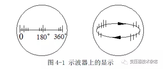
1, partial discharge waveform analysis, detection impedance Zm on the voltage (that is, the detection signal) is quite small, must be amplified to make the instrument has obvious indication. The peak value of the pulse signal amplified by the amplifier can be measured by the OSCILLOSCOPE. In addition, the OSCILLOSCOPE can also see what phase the discharge occurs at the power frequency, measure the pulse waveform and discharge times, and observe the characteristics of the whole partial discharge. To determine the approximate location and nature of the discharge. The OSCILLOSCOPE can be scanned horizontally and elliptically. The full-screen deflection of the horizontal scan corresponds to a period and is synchronized with the test voltage to determine the phase of the pulse. Elliptical scanning is also equivalent to one test voltage cycle per scan week. Figure 1-is A schematic of the waveform on the screen during both scans.
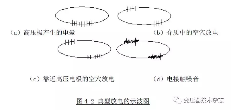
在局部放电试验时,除绝缘内部可能产生局部放电外,引线的联接,电接触以及日光灯,高压电极的电晕等,也可能会影响局部放电的波形。为此,要区别绝缘内部的局部放电与其他干扰的波形,图1-2就是几种典型的波形。
2. The pattern recognition figure 1-3 of partial discharge is different types of partial discharge oscillograms, which are obtained near the starting voltage. The diagrams (a) , (B) , (c) and (d) are the basic diagrams of partial discharge, and (e) , (F) and (g) are the basic diagrams of interference wave.
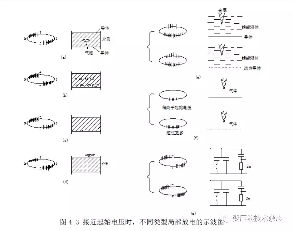
(a) in the insulation, there is only one air gap perpendicular to the electric field, the discharge pulse is superimposed between the positive and negative peaks, and the amplitude and frequency of the two symmetrical pulses are basically equal. But sometimes an asymmetry of 3:1 between the upper and lower ranges is normal. The relation between the discharge quantity and the test voltage is that after the initial discharge, when the discharge quantity increases to a certain level, the discharge quantity remains unchanged as the test voltage rises. The quenching voltage is basically equal to or slightly lower than the starting voltage. (B) , the insulation structure contains a variety of different sizes of air gap, mostly pouring insulation structure. The amplitude and frequency of the two symmetrical pulses are almost the same, but sometimes the asymmetry of the up and down amplitude is 3:1. At the beginning of the discharge, the discharge pulse can be distinguished, then the voltage rises, some discharge pulses move towards the zero position of the test voltage, at the same time, the pulse with larger amplitude will appear, the pulse resolution will gradually decrease, until it can not be distinguished. After the initial discharge, the discharge quantity increases steadily with the increase of voltage, and the quenching voltage is basically equal to or lower than the initial voltage. (C) in the insulation structure, the discharge response of the electrode surface with only one air gap is different from that of the dielectric inner air gap. The discharge pulse is superposed before the positive and negative peak of the voltage, the amplitude of both sides is not symmetrical, the frequency of large amplitude is low, the frequency of small amplitude is high. The ratio of the two values is usually greater than 3:1, sometimes up to 10:1. The total discharge response can be distinguished. Once the discharge starts, the discharge amount is basically unchanged, independent of the voltage rise. The extinction voltage is equal to or slightly below the starting voltage. (D) in which (1) a cluster of air gaps of different sizes is located on the surface of the electrode, but is of a closed type; (2) the surface discharge gap between the electrode and the insulating medium is not closed. The amplitude ratio of the two sides is usually 3:1, sometimes up to 10:1. As the voltage rises, part of the pulse moves towards zero. After discharge, the pulse resolution is acceptable, and the voltage is increased, the resolution is decreased until it can not be resolved. After the initiation of discharge, the discharge voltage increases with the increase of voltage, and the extinction voltage is equal to or slightly lower than the initiation voltage. If the voltage, the duration of 10 minutes later, the discharge response will be some changes. (e) the source of interference is a liquid medium with the tip of a pin against a flat plate or the ground. Corona discharge is produced at lower voltage, and the discharge pulse is superposed to the peak of voltage. If located at a negative peak. The discharge source is at a high potential; if it is at a positive peak, the discharge source is at a low potential. This can help to determine the voltage zero, a pair of pulse symmetry in the voltage positive or negative peaks, each cluster of discharge pulse time interval are equal. But the amplitudes and time intervals of the two clusters are different, and the smaller clusters have the same amplitudes and are more dense. The starting voltage of a larger pulse is lower, and the discharge quantity increases with the increase of the voltage; the starting voltage of a smaller pulse is higher, and the discharge quantity is independent of the voltage and remains unchanged; the frequency density of the pulse increases with the increase of the voltage, but it is still distinguishable; It's becoming indistinguishable. (F) gas medium with tip against flat plate or ground. Corona discharge is produced at lower voltage, and the discharge pulse is superposed to the peak of voltage. If it is located at the negative peak, the discharge source is at high potential; if it is located at the positive peak, the discharge source is at low potential. This helps determine the zero of the voltage. After the initial discharge, the voltage rises and the discharge quantity remains the same, but the pulse density diffuses to both sides and the discharge frequency increases, but it is still distinguishable. (G) suspended potential discharge. A discharge between two suspended metal objects in an electric field or between a metal object and the earth. There are two kinds of waveforms: 1 the positive and negative two-sided pulses have the same amplitude, the same interval and the same frequency; 2 the two-sided pulses appear in pairs with the same interval, sometimes they move back and forth in the baseline. There are three types after the initial discharge: (1) the discharge quantity remains unchanged, independent of the voltage, and the quenching voltage is exactly equal to the initial voltage. (2) the voltage continues to rise, at a certain voltage, the discharge suddenly disappears. After the voltage continues to rise, the discharge will again appear under the previous vanishing voltage. (3) as the voltage rises, the discharge quantity gradually decreases and the discharge pulse increases.

Hotline
+86-185-5293-9138
work shift
from Monday to Friday
Company phone
+86-185-5293-9138
 Service