Release time:2021-03-26 16:04:32 Popularity: Source:未知
Light high-voltage transformer calculation, dry-type transformer use, high and low-voltage switchgear inspection project light high-voltage transformer transformer transformer about transformer calculation formula

Calculate the number of turns per volt and the wire diameter of the transformer according to the power and voltage required. Small and medium-sized transformers use power to calculate the cross-section area of the core (the part with the coil) : s = 1.25 P (s = core cross-section: C M2, P = power: W) TURNS PER VOLT: n = 4.5100000 BG S (BG = core permeability, usually between 6000 and 12000 Gauss, when the core permeability is not examined, generally according to the recent production of iron core permeability in the vicinity of 10000 Gauss) , when the permeability is 1000 Gauss, the formula is simplified as: When n = 45/s is used to calculate the diameter of the wire, the first and the second order can calculate the diameter of the wire according to the output current according to the power. Find Current: I = P/u Find Line diameter: d = 1.13 root number (I/)(d = line diameter: M M2, = current density: 2.5 ~ 3A, generally take 2.5 a) electrical encyclopedia: dry-type Transformer Safe Operation and service life
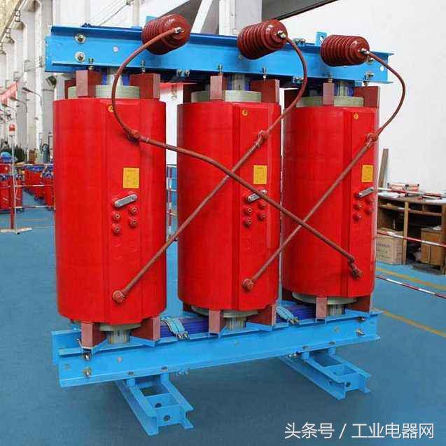
The Safe Operation and service life of dry-type transformer largely depend on the safe and reliable insulation of transformer winding. It is one of the main reasons that the dry-type transformer can not work normally, so it is very important to monitor and control the operating temperature of the transformer, the TTC-300 series temperature control system is briefly introduced. (1) Fan automatic control: take temperature signal by PT100 thermistor which is embedded in the hottest place of low voltage winding. When the winding temperature reaches 110 °c, the system automatically starts the Fan Cooling; when the winding temperature reaches 90 °c, the system automatically stops the fan. (2) over-temperature alarm and trip: The temperature signal of winding or core is acquired by PTC non-linear thermal resistance embedded in low-voltage winding. When the winding temperature of the dry-type transformer continues to rise, if the temperature reaches 155 °c, the system outputs an over-temperature alarm signal; if the temperature continues to rise to 170 °C, the transformer can not continue to operate, the over-temperature trip signal must be sent to the secondary protection circuit, the transformer should be tripped quickly. (3) temperature display system: by measuring the temperature change value of PT100 thermistor embedded in the low-voltage winding, the temperature of each phase winding can be directly displayed (three-phase inspection and maximum value display, and record the highest temperature in history) , the maximum temperature can be output in 4 ~ 20mA analog quantity, if need to transmit to remote computer (distance can be up to 1200m) , can be equipped with computer interface, 1 transmitter, can monitor up to 31 transformers simultaneously. The over-temperature alarm and trip of the system can also be actuated by PT100 thermistor signal to further improve the reliability of the temperature control and protection system. Inspection items of high and low voltage switchgear

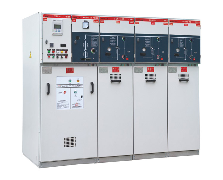
Cabinet Assembly Inspection 1. Cabinet width, depth and height meet the drawing requirements, diagonal dimension deviation ≤ ± 2mm; other key parts of cabinet size meet the requirements; 2. Cabinet various types of connectors, installation plates, rings, etc. , installation is correct, joint fastening. 3. The front and back doors open and close freely, and the opening angle of the doors is 90 ° . 4. No scratch, crack, bubble and other phenomena of the cabinet paint, uniform color and luster, in line with the requirements. 5, the door, door lock, hinge, lock Rod, etc. Are installed correctly, the gap refused; the door, seal plate and so on have no shaking phenomenon. 6, Cabinet, instrument panel, door panels and other good grounding, good grounding, no paint and other dirt grounding bolts. 7. Protective measures should be taken for the installation plate, bracket and cable holes which are easy to cause human operation injury or conductor injury. 8, Clean Cabinet, no foreign matter; sealing plate, the surface inside and outside the door without oil stains, dirt, dust and other garbage. Component Installation Inspection 1. Component model and specification meet drawing requirements. 2, components installation location, installation mode and other components in line with the installation requirements and technical requirements. 3. The gap between the surface plate of circuit breaker body and the surface plate of cabinet body is uniform, the gap size deviation ≤ ± 1mm; 4. The fixing bolt (screw) , flat pad, Spring, nut and other specifications are suitable; the torque value of fastening bolt meets the requirements; THREAD EXPOSED NUT 2 ~ 5 wires, nut on maintenance side. 5, all kinds of components have accessories, accessories should be installed complete, solid, correct. 6, all kinds of components inside, surface without iron filings, thread head, ribbon and other garbage, clean up. Third, the secondary wiring inspection 1, components identification, terminal circuit name identification integrity, correct, neat and beautiful, in line with the requirements. Terminal label is complete and correct. 3, wire at both ends of the wire number; wire number position is correct, NEAT and beautiful. 4, wiring must be neat and beautiful, balance vertical, in line with the requirements of the process specifications. 5. The electric gap and creepage distance in the secondary circuit should meet the requirements of the secondary wiring construction code. 6, the wire through the metal clapboard, Busbar, instrument door wire fixed point, secondary wire should be treated for protection. The length of the handle of the instrument door is moderate, so that the door can be opened and closed freely. 7, the choice of various types of copper terminal size, specifications in line with the components terminal wiring mode. The crimping method of the copper joint is correct, and the crimping is firm. Wiring Bolt Screw, flat pad, Spring and other specifications consistent with the requirements; bolt fastening, thread exposed nut 2 ~ 5 teeth; 9, the same batch of production contracts, to leave the wire length moderate, fixed position unity. If the Earth Line, N line, power line and other available diameter of about 6mm round metal objects, wire winding 3 ~ 5 times. 10, the secondary wiring must be in accordance with the drawing construction, wiring correct, in line with the drawing requirements. The reserved position of terminal wiring is correct and uniform. 11, the secondary excess head should be timely wrapped, hidden treatment, and fixed; wiring harness must not have bare head. 12, wiring after completion, thread head, ties and other foreign bodies should be cleaned in a timely manner. One-time wire production installation inspection 1, wire selection of the model, the correct specifications; wire phase sequence connection is correct. 2. The two ends of the wire are marked with phase sequence; the phase sequence marks are neat, beautiful and firm. 3, the conductor joint specification selects correctly, the compression connection method is correct, firm. 4, wire length moderate, connection natural fit, fixed position, correct way, NEAT and beautiful. 5, Wire Connection Bolt Screw, flat pad, Spring, nut and other appropriate specifications; fastening Bolt Torque value to meet the requirements, thread exposed nut 2 ~ 5 wire, nut placed in the maintenance side. 6. When the conductor meets the metal edge mouth, the metal hole, the metal edge mouth should do the protection processing. 7. When the conductor meets the heating element and the main bus, the conductor should keep not less than 5cm distance from the heating element, such as the reactor, the heater, etc. . 8. The electrical clearance and creepage distance of the main circuit meet the requirements. The electric gap between different conductive points is not less than 10 mm, the creepage distance is not less than 12.5 mm. 9, wire should not be more bundle tied; reserve wire position is correct, length is moderate, neat and beautiful, fixed and reliable. Mechanism Installation Inspection 1, high-voltage circuit breaker, low-voltage drawer and other moving contacts, a moderate amount of neutral lubricating grease; circuit breaker, low-voltage drawer in and out of flexible operation, no stuck phenomenon. 2, high and low pressure mechanism, guide rail, etc. Are installed correctly and fixed reliably. The earthing switch and opening are flexible and the closing and opening marks are correct. The earthing knife is provided with neutral lubricating grease. 3. The interlock function of the high-pressure mechanism can meet the requirements of "five prevention interlock" . 4, high-pressure cabinet valve mechanism installation is correct, reliable action, rise and fall without deviation. 5. The operation mechanism of low-voltage switch-off is correctly installed, fixed reliably, operated flexibly, and meets the interlock requirements of the mechanism;. Moderate amount of neutral lubricating grease is available in the moving parts of the mechanism. 6. The handcart, drawer, circuit breaker and so on of the same function unit should be interchangeable reliably. Bus Installation Check 1, bus phase sequence is correct, the first program in line with the drawing requirements, in and out of the bus space reserved, the position is correct, in line with the requirements. 2, busbar phase sequence label paste integrity, correct, NEAT and beautiful. 3, bus surface flat, no cracks; Connection Hole, bus section, section should be no BURR, etc. . 4. The specification of the connecting bolt (screw) , flat pad, Spring and nut is suitable, the torque value of the fastening bolt is in line with the requirement, the screw shows 2 ~ 5 threads of the nut, and the nut is placed on the maintenance side. 5, the busbar connection Bolt Fastens, the bolt has the black fastening mark line, the mark line mark conforms to the request. 6. The electrical clearance and creepage distance of the main bus meet the requirements. The electric gap of low voltage cabinet is not less than 20mm, the creepage distance is not less than 25mm. High Voltage 6 kv electrical gap not less than 100 MM, 10 KV electrical gap not less than 125 mm. 7, the main bushing heat shrinkable specification is correct, no damage, wrinkling, cutting surface neat. 8, bus connection surface flat, no foreign body, connection natural fit, reliable; request connection surface brush conductive paste, should be uniformly coated thickness of about 0.3 mm, after connecting, excess conductive paste wipe clean. The connecting piece used for connecting primary or secondary wires is in the correct direction and position. Other Inspection 1, instrument door sign, drawer sign, eyebrow cabinet sign, factory sign, analog sign, etc. , complete, neat and beautiful, firm, in line with the drawing requirements. 2. If it is necessary to mark the model, specification, circuit or phase sequence of the circuit, the mark should be complete, neat, beautiful and correct. 3. The bus frame, grounding bracket, cable bracket, insulator, etc. are properly installed and firm. The arrangement and combination of switch cabinet accord with the drawing requirements. 4, Pe row, N row, one-time adapter and other accessories need with bolts is, the number of bolts, specifications should be correct. Electrical Encyclopedia, industrial sites, electrical headlines, the world of electricity I know best!。

Hotline
+86-185-5293-9138
work shift
from Monday to Friday
Company phone
+86-185-5293-9138
 Service